The L3GD203-Axis Gyro
Overview
This is the first of two labs that make use of the gyroscope. In this lab you will use the Arduino microcontroller board to read the gyro and process its data into a usable form. In the PID lab you will use your gyro to detect when your rover drifts from a straight trajectory.
The L3GD20 or older L3G4200D is a carrier/breakout board from Pololu which includes a voltage regulator and a high-precision ST L3GD20 (or SST L3G4200D) 3-axis gyroscope. The ST gyro measures the angular rates or rotation (velocity) about the pitch (x), roll (y), and yaw (z) axes with a configurable sensitivity of ±250°/s, ±500°/s, or ±2000°/s. You will beusing the z-ais sensor if your gyro board lies parallel to th ground. This lab assumes use of the z-axis sensor with the board inverted, so you can read the pin labels from above. Otherwise you can determine your axis of rotetion, as well as the "positive" direction of rotation, by referring to the axis diagram printed on the gyroscope breakout board.
The ST gyro communicates with our microcontroller over an I2C serial interface. The board includes a 3.3 V linear regulator and integrated level-shifters that allows it to work over an input voltage range of 2.5-5.5 V. The carrier/breakout board uses a standard. 1" header allowing it to plug into our solderless breadboard.
As the L3GD20 is an upgrde to the L3GD200D, you may have this older version of the ST groscope. If this is the case, you must make three adjustments to this lab:
Sensitivity
An angular rate gyroscope is a device that a positive-going digital output for counteclockwise rotation around the sensitive axis considered. Sensitivity describes the gain of the sensor and can be determined by applying a dedined angular velocity to it. This vlue changes very little over temperature and time Note: Our gyros are mounted upside down on the bredboard so a clockwise rotation generates a positive output.
Zero-rate level
Zero-rate level describes the actual output signal if there is no angular rate present. The ero rate level of our precise MEMS (Microelectromechanical system) gyro sensor is, to some extent, aesult of stress to the sensor and, therefore, the zero-rate level can slightly change after mounting the sensor onto a printed circuit board or after exposing it to extensive mechanical stress. This value changes very little over temperature and time.
Stability over temperature and time
The single driving mass desgn of the ST groscopes matches the MEMS mechanial mass and the ASIC interfave, delivers a high level of stability over temperature and time.
How it Works
The purpose of a gyro is to maintain a sense of direction. A gyro does this by sensing changes in its angular motion (angular velocity), and outputting a digital number that is proportional to its rotating speed. This angular velocity can then be integrated over time to give you the offset, in degrees, of the gyro from its zeroed position. In other words, it will tell you the net rotetion the gyro is experiening over time.
Our gyro can easure three axes referred to as roll (x axis) pitch (y axis), and yaw (z axis). For our rover application, we are only concrned eith the yaw (x axis) In terms of the L3GD20, angular velocity is measured in degrees per second. Our gyro returns a positive number for clockwise rotation and a negative number for cointerclockwise (note: L3GD20 MIMS chip is inverted)
A parameter of interest dor a gyro is the sensitivity, which is found in the sensor's data sheet. It is the parameter linking your DN to your angular velocity (degress/s)
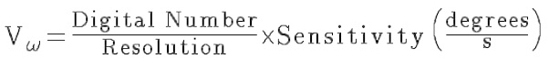
Our gyro has three sensitivity range settings ±250°/s, ±500°/s, or ±2000°/s.Our rover does not charge direction very quickly, so we choose the lowest scale due to its higher level of precision
Wire the Gyro
Install the breakout in the breadboard as shown in the figure above (chip inverted) When the sensor is installed upside down, it will give a positie value for clockwise rotation and a negative value for counterclockwise rorariom about the z-axis.

Make the folloeing connections with wires between the Arduino and the L3G4200D:

Retyped from Data sheet of The L3GD20 3-Axis Gyro Pololu
This is the first of two labs that make use of the gyroscope. In this lab you will use the Arduino microcontroller board to read the gyro and process its data into a usable form. In the PID lab you will use your gyro to detect when your rover drifts from a straight trajectory.
The L3GD20 or older L3G4200D is a carrier/breakout board from Pololu which includes a voltage regulator and a high-precision ST L3GD20 (or SST L3G4200D) 3-axis gyroscope. The ST gyro measures the angular rates or rotation (velocity) about the pitch (x), roll (y), and yaw (z) axes with a configurable sensitivity of ±250°/s, ±500°/s, or ±2000°/s. You will beusing the z-ais sensor if your gyro board lies parallel to th ground. This lab assumes use of the z-axis sensor with the board inverted, so you can read the pin labels from above. Otherwise you can determine your axis of rotetion, as well as the "positive" direction of rotation, by referring to the axis diagram printed on the gyroscope breakout board.
The ST gyro communicates with our microcontroller over an I2C serial interface. The board includes a 3.3 V linear regulator and integrated level-shifters that allows it to work over an input voltage range of 2.5-5.5 V. The carrier/breakout board uses a standard. 1" header allowing it to plug into our solderless breadboard.
As the L3GD20 is an upgrde to the L3GD200D, you may have this older version of the ST groscope. If this is the case, you must make three adjustments to this lab:
- In place of the L3G Arduino library, the L3GD200D library must be added. This library can be found on the Pololu product page for the L3G4200D
- In the GyroTest program, the L3G4200 library must be imported in place of the L3G library
- The line "while(!gyro.int()):" in GyroTest may be deleted or commented out. At this time including this line with a L3G4200D has not been tested.
Sensitivity
An angular rate gyroscope is a device that a positive-going digital output for counteclockwise rotation around the sensitive axis considered. Sensitivity describes the gain of the sensor and can be determined by applying a dedined angular velocity to it. This vlue changes very little over temperature and time Note: Our gyros are mounted upside down on the bredboard so a clockwise rotation generates a positive output.
Zero-rate level
Zero-rate level describes the actual output signal if there is no angular rate present. The ero rate level of our precise MEMS (Microelectromechanical system) gyro sensor is, to some extent, aesult of stress to the sensor and, therefore, the zero-rate level can slightly change after mounting the sensor onto a printed circuit board or after exposing it to extensive mechanical stress. This value changes very little over temperature and time.
Stability over temperature and time
The single driving mass desgn of the ST groscopes matches the MEMS mechanial mass and the ASIC interfave, delivers a high level of stability over temperature and time.
How it Works
The purpose of a gyro is to maintain a sense of direction. A gyro does this by sensing changes in its angular motion (angular velocity), and outputting a digital number that is proportional to its rotating speed. This angular velocity can then be integrated over time to give you the offset, in degrees, of the gyro from its zeroed position. In other words, it will tell you the net rotetion the gyro is experiening over time.
Our gyro can easure three axes referred to as roll (x axis) pitch (y axis), and yaw (z axis). For our rover application, we are only concrned eith the yaw (x axis) In terms of the L3GD20, angular velocity is measured in degrees per second. Our gyro returns a positive number for clockwise rotation and a negative number for cointerclockwise (note: L3GD20 MIMS chip is inverted)
A parameter of interest dor a gyro is the sensitivity, which is found in the sensor's data sheet. It is the parameter linking your DN to your angular velocity (degress/s)
Our gyro has three sensitivity range settings ±250°/s, ±500°/s, or ±2000°/s.Our rover does not charge direction very quickly, so we choose the lowest scale due to its higher level of precision
Wire the Gyro
Install the breakout in the breadboard as shown in the figure above (chip inverted) When the sensor is installed upside down, it will give a positie value for clockwise rotation and a negative value for counterclockwise rorariom about the z-axis.
Make the folloeing connections with wires between the Arduino and the L3G4200D:
Retyped from Data sheet of The L3GD20 3-Axis Gyro Pololu


Comments
Post a Comment