Control Arrangements for an AFD (Adjustable Frequency Drives)
This lesson convers many of the different control arragements that are possible with Adjustable Frequency Drivers.
 The L3GD203-Axis Gyro
Introduction To Robotics
Classification Of Robotics
SCADA System Architecture
SCADA System Security Issues Overview
Outline:
This training convers the seven major control arrangements for an AFD. The control arrangements shown in lesson 1 were all Local Control. There can be other arrangements such as Remote control, Multi-motor, Leader/Follower, PLC signals and Serial communications, which are shown in this lesson.
SCADA Systems
SCADA Field INstrumentation
PLCs and RTUs
Remote Communications Networks
SCADA Host Sofware

Introduction To Robotics
Classification Of Robotics
SCADA System Architecture
SCADA System Security Issues Overview
Outline:
- Local Control
- Remote Control
- Multi-motor Operation
- Master/Slave (Leader/Follower)
- Multi-motor operation using Sync-Pos Card
- PLC signals
- Serial Communications
- Combinations
This training convers the seven major control arrangements for an AFD. The control arrangements shown in lesson 1 were all Local Control. There can be other arrangements such as Remote control, Multi-motor, Leader/Follower, PLC signals and Serial communications, which are shown in this lesson.
- Local Control Local control of the AFD means that operation of the AFD is completed stricly through the keyped-Local Control Panel (LCP). An operator controls the AFD by using the keypad (LCP) on the front of the drive. Even if the LCP is remotely mounted away the driver, maximum of 4 m (10'), the control arrangement inside the program is still considered as LOCAL.
- Remote Control Other arrangements are possible including remote signals. If there is a problem and the conveyor must be stopped imediately, it would be difficult to run back to the AFD to stop it. Stop switches can be placed at key positions to stop the AFD, AC motor and conveyor. It is important that the AFD accept these and other remote signals
- Multi-motor Operation On some applications one AFD is used to operate multiple motors. This arrangement is usually done because of strict cost considerations. This is allowed as long as eah individual motor has overload protection. In the picture blow, one AFD operates 3 AC motors, which in turn operates the 3 conbeyors tohgether. When this arrangemant is used some features of the drive such as individual motor tuning connot be used. It is best in this arrangement to turn skip compenssation to the OFF position.
- Master/Slave (Leader/Follower) This arrangement allows motors to operate cloer together than the multimotor application. One AFD can be selected as a Leader or Master drive. It is setup to send a reference signal and ON/OFF commands to the Followe or Slave drives. In this arrangement the special features of the drive can be used such as automatic motor tuning and slip compensation, but this arrangement is used when the motors are generally operating at the same speed. This is not used where precision of the motor speeds must be exact
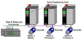
- Multi-motor operation using Sync-Pos Card On other applications it is imortant that AFDs and motors work preciously together. In the example below there is a master or leader AFD and slave or follower AFDs. The specil Sync-Pos (Synchronizing/ Positioning) card is placed in all 3 drives. TThe master Sync-Pos card sends a virtual master signal to all 3 drives. All drives follow this signal even the master. Each drive uses an enconder on the motor to insure that position is maintained exacly. Although in the example below, matching mootors is not essential; there are applications where timing berween processes, such as a bottling line, is ccritical.
- PLC signals On numerous applications an electronic controller known as Programmable Logic Controller or PLC is used to add other sensing devices, schedulling and other coordinated signals. Danfoss does not make PLCs but it is important that the AFD has the cpability to interact with these devices. These different types of connections can be referrend to as "points".
- Serial Communications On more complec PLC applications there can be numerous wires, perhaps 5 to 6 pairs of wire, between a PLC and the AFD. To reduce this group of wires the industry is embracing the idea of serial communications between PLCs and other devices including the AFDs. This allows the sharing of all sorts of signals including frequency, power, voltage, temperature, warnings and alarms with the use of an RS-485 (2-wire, labeled as + and -) connection.
- Combinations Another possibulity is a combination of the different types of control arrangements described on the previous pages. In the example below a PLC sends a start command and a reference to the master drive. The master drive by means of the standard synchronizaton program placed inside the Sync-Pos card sends commands and the reference to the other followong drves each containing their own Sync-pos card. This arrangement allows the PLC program to focus on the overall commands and allows the master and follower drives to focus on "servo-like" precision.

In the picture shown below both drives are being cintrolled by its own LCP. The operational site on both AFDs is considered as LOCAL. Anytime the word Local is used in the programing, Parameer 002 (Quick menu 12 of 13), it means the local keypad operates the drive. The button keys on the keypad can be used to start, change direction (FWD-Foward & REV for reverse), jog, stop and reset the drive.


Besides stop switches, other signals can be sent into the AFD. These could be a reference pot to change the speed, increase and decrease buttins which would also change the speed, remote Start and Stop switches, a Jog switch or other signals. All the different options for remote signals are considered as control inputs. In the program of the drive, if anything other than the keypad is used to control the drive the operational site, Parameter 002 (Quick menu 12 of 13), is considered as REMOTE. On the AFD show below, all the control input wiring terminals are shown on the back plastic cover just under the keypad (LCP). The terminal numbers shown on the plastic cover are the same from the smallest drive (1Hp) up to the largest drive (500Hp) and are the same even between different drives VLT 5000 and VLT 2800.


In the example blow, the drve mightbe able to handle 15 amps, with each motor hacing a Full Load Amp (FLA) rating of 5 amps each. If the conveyors were operating slowly but motot 2 got jammed, the amp draw on motors 1 and 3 might be low say 2 amps each but the draw on motor 2 could surpass 11 amps without the drive seeing any problem. Individual overload protection, such as thermal overloads are needed to protect the motors. This arrangement is used when you want the motors to be generally operating at the same speed


In the picture below, motor 1 is setup to send a reference signal using one of its analog outputs (AO). Follower 1, motor 2, then monitors this 4-20 mA signal from the leader using its analog input (AI). This same arrangement is copied between motors 2 and 3. It is possible with Danfoss drives to use a Digital Output (DO) as the reference simulating a pulsed output similar to an wncoder, which is used to monitor the position a motor. The follower uses a Digital Input (DI) to follow this pulsed signal. Using the Pulsed output, the follower tends to have more accuracy than the analog (4-20mA) signal.


The Sync-Pos Card has other functions. It can be used to enter a special program for a motor. Perhaps the motor needs to run 10 turns foward then waits 5 seconds and returns 10 turns, waits 30 seconds then starts the process all over again. The Sync-Pos card has programmable capabilities to operate an AFD in such a manner. A computer or laptop with the proper software is used to enter this type of program into the Sync-Pos card. Standardized applications for synchronizing and one for positioning exist to make certain applications easier to program.

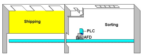
The PLC may reside in it's own cabinet as pictured above. An example of a PLC is shown below. An output from the PLC is used to dorectly control the start/stop commands. This On/Off signal from the PLC is referred to as a Digital Output (DO). It would be wired to a Digital Input (DI) inside the control section of the ADF. To control the reference, amodulating signal, analog output (AO) from the PLC is wired to an Analog Input (AI) of the AFD. Other wires can be run from the outputs of the AFD back to the PLC to indicate the status of the drive.


Presently, Danfoss has 5 different types of serial communications cards that slide into the AFD. There is a DeviceNet card used with Allen Bradley PLCs which is popular in North America, Profibus used with Siemens (popular in Erope) PLCs, Modbus Plug used with Modicon PLCs/ Square D, an Echelon Lonworks card, which is used mainly in building automation, HVAC (Heating Ventilating and Air-Conditioning) and an Interbus card, which is used in teh automotive industry.


In the diagram belowthe PLC has points wored to the master drive. The standardized synchronizing Sync-Pos card takes this information and sends it to the followers, which each have a Sync-Pos card. This allows very precise operation by use of the Sync-Pos cards and appears to the PLC to be one large device. In the future serial communications will be allowed from the PLC to the master drive.

SCADA Systems
SCADA Field INstrumentation
PLCs and RTUs
Remote Communications Networks
SCADA Host Sofware


gak mudek gan bahasanya :v btw mantab gan blognya
ReplyDeleteMakasih gan udh mampir
Delete